| Publication number | US3814418 A |
| Publication type | Grant |
| Publication date | Jun 4, 1974 |
| Filing date | Apr 27, 1973 |
| Priority date | Feb 7, 1972 |
| Publication number | US 3814418 A, US 3814418A, US-A-3814418, US3814418 A, US3814418A |
| Inventors | Henning S |
![]()
For more information, contact us slides@dunriteplaygrounds.com
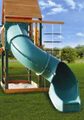
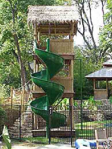
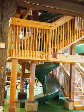
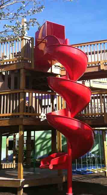
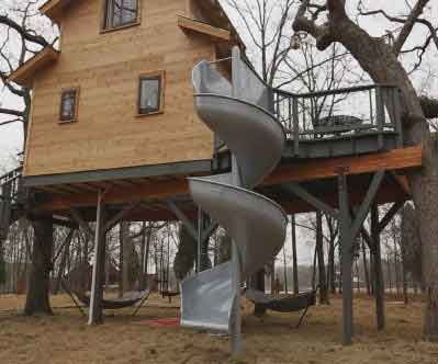
Helical
slide PATENT
US 3814418 A
 |
 |
 |
 |
 |
 |
 |
|
 |
 |
||
United States Patent [1 1 Henning [45] June 4, 1974 [73]
221 Filed: Apr. 27, 1973 211 Appl. No.: 355,197
Related US. Application Data [62] Division of Ser. No. 224,108, Feb. 7, 1972.
[52] US. Cl. 272/565 R, 193/12 [51] Int. Cl. A63g 21/00 [58] Field of Search 272/565 R, 56.5 SS, 60;
193/2, 12, 13; 29/1568 R, 157.3 AH, 469; 182/48; D34/5 E; 104/56, 57, 69, 70
[56] References Cited UNITED STATES PATENTS 506.238 10/1893 Kirker 193/12 629.597 7/1899 Pardee 193/12 X 803,119 10/1905 Logan t t 272/565 R 1,959,736 5/1934 Rademacher 193/12 UX D218,625 9/1970 Ahren t D34/5 E 3,565,226 2/1971 Winchester 193/12 OTHER PUBLICATIONS General Playground Equipment,Inc., Kokomo, Indiana, Catalog No. 22. Page 2, Fun-Ful Spiral Slide, 1948.
Haslett Spiral Chutes Brochure 1953, Haslett Chute and Conveyor Company, Oaks, Pennsylvania Primary ExaminrAnt0n O. Oechsle Assistant Examiner-Arnold W. Kramer Attorney, Agent, or Firm-Trask, Jenkins & Hanley [57] ABSTRACT A slide and method of making it in which there is an upright ground-engageable post having a helical channeled bedway extending axially therealong with a ladder interconnected to the upper end of said bedway. The bedway is formed from an annular body having inner and outer radially spaced circumferential edges. After the body is formed, it is cut there across, a post is inserted through said body, and the inner circumferential inner edge of said body adjacent one of its ends is connected to said post. The opposite end of said body is pulled axially along the post to cause said body to project radially outwardly therefrom with its inner circumferential edge abutting said post along a helical path. Said inner circumferential edge is fastened to the post, and the ladder is then interconnected to the upper end of the extended bedway.
2 Claims, 7 Drawing Figures HELICAL SLIDE BACKGROUND OF THE INVENTION Helical slides and chutes in which the slide bedway or channel is in the form of a helix mounted on a vertical support running along the axis of the helix are known in the art. Such slides are shown in my prior U. S. Pat. Des. No. 221,963 and in U. S. Pat. Nos. 1,256,724; 2,437,259; 1,270,366 and 3,083,015.
In the manufacture of such slides, it has heretofore been the conventional practice to form the channel shaped bedway of the slide from a plurality of small pie shaped sections which are connected to each other and to the center supporting post. Because of the small radial extent of the inner ends of these various sections, it has been necessary to brace such sections and the bedway formed thereby with braces extending from the sections inwardly to the supporting post or by groundengageable braces projecting outwardly and downwardly from the bedway.
The instant invention overcomes the difficulties and disadvantages of such prior construction methods by providing a method of making a spiral slide in which the channeled bedway is formed from a limited number of parts which can be easily connected to each other and to the central supporting post thereby effecting economies in the manufacture of the slide and reducing the number of interconnections that must extend across the bedway.
SUMMARY OF THE INVENTION In accordance with the preferred form of the invention, there is first formed an annular body having a generally U-shaped cross-section between its inner and outer circumferential edges. A radial cut is made across the body between a pair of points on its inner and outer circumferential edges to thus form a pair of ends on said body. An elongated ground-engageable post is inserted through the body, and the inner circumferential edge of said body adjacent one end thereof is fixedly connected to said post. After the connection is formed, the opposite end of the body is pulled axially along said post to thus cause said body to project radially outwardly from the post with its inner circumferential edge abutting said post along a helical path. The inner circumferential edge is rigidly fastened to the post with the body forming a spiral bedway extending downwardly along the post.
A platform assembly is connected to said body at the upper end thereof, and a ground-engageable ladder is connected to said platform assembly. The lower end of the helical bedway terminates above the lower end of the ground-engageable post, and desirably, a U-shaped discharge chute is mounted on the lower end of said bedway to project generally tangentially outwardly from said post.
BRIEF DESCRIPTION OF THE DRAWINGS The accompanying drawings illustrate the invention. In such drawings:
FIG. 1 is a side elevation of a slide according to the instant invention, with portions thereof being broken away;
FIG. 2 is a top plan view of the slide shown in FIG. 1;
FIGS. 3-6 show the successive steps for forming and mounting the channeled bedway on the slide shown in FIG. 1; and
FIG. 7 is a side elevation of a slide similar to the one shown in FIG. 1, but showing a modified form thereof.
DETAILED DESCRIPTION OF THE PREFERRED EMBODIMENT As shown in FIG. 1, my novel slide construction comprises a spiral bedway 10 projecting radially outwardly from and extending axially along a ground-engageable center support post 12. A discharge chute 14 is mounted on the lower end of the bedway 10, and a platform assembly 16 is mounted on the upper end of said bedway. A ground-engageable ladder assembly 18 is mounted on the outer end of the platform assembly 16 and angles downwardly therefrom.
As shown in FIGS. 3-5, the bedway 10 is formed by forming a circular disc 20 into an annular body 22 having inner and outer circumferential edges 23 and 24. The body has a generally U-shaped cross-section between the edges 23 and 24 to give it a channeled cross section. This cross-sectional configuration is provided by an inner wall portion 25 whose inner edge constitutes the inner circumferential edge 23 and an outer wall portion 26 whose outer edge constitutes the circumferential edge 24. The inner and outer wall portions 25 and 26 are interconnected by a floor portion 27 which forms the bottom or floor of the bedway 10. As shown, the outer wall portion 26 has an axial extent substantially greater than the axial extent of the inner vwall portion 25. Desirably, in forming the body 22, the
outer circumferential edge 24 is rolled to form a bead 28 extending therealong.
After the body 22 has been formed into the configuration illustrated in FIG. 4, a radial cut 30 is formed in said body as illustrated in FIG. 5. As shown, the cut 30 extends from a point on the inner circumferential edge 23 radially outwardly to an adjacent point on the outer circumferential edge 24. In this manner, the body is provided with a pair of ends 32 and 33. As shown in FIG. 6, after the cut 30 has been formed, the elongated post 12 having a ground-engageable foot 37, is inserted through the center of the body 22. Said post has an outer circumference substantially less than the length of the circumferential edge 23. With the post inserted through the body 22, the inner circumferential edge 23 of the body, adjacent its end 33, is rigidly fastened to said post, as at 38. As shown in FIG. 6, the connection 38 is disposed adjacent to but downwardly from the upper end of said post.
It is also possible to insert the post 12 through the body 22 prior to forming the cut 30 therein. However, in most applications it is easier to manipulate and handle the body to form said cut prior to inserting the post through said body. 1
After the connection 38 has been made, the free end 32 of the body 24 is pulled downwardly along post 12 as indicated by the arrow A. This downward pulling effort causes the body to rotate around the axis of the post 12 with its inner circumferential edge 23 abutting said post along a helical path. Desirably, the body 22 is extended axially along post 12 a distance sufficient that said body forms one revolution around said post.
. With the body maintained in its extended helical configuration, its inner edge 23 is rigidly fastened to the post. With the body rigidly connected to the post, the
connected to the post 12, the discharge chute 14 is rigidly connected to the lower end 32 of said bedway to project tangentially outwardly from the post. As shown, said chute has a generally U-shaped configuration, and is thus provided with inner and outer wall portions 42 and 43 connected to wall portions 25 and 26 and a floor portion 44 connected to the floor portion 27.
The platform assembly 16 is then mounted on the upper end 33 of the bedway. As shown in FIGS. 1 and 2, said platform assembly comprises a platform 46 having a U-shaped cross-section formed from a pair of side walls 48 and 49 interconnected by a floor 50. The inner end of the wall 49 is connectedto the outer wall portion 26, while the inner endof the platform wall 48 is connected to the post 12. A generally frustoconical transition section 55 is connected to the inner edge of the platform floor 50 and to the inner wall portion 25, floor portion 27 and a portion of the outer wall portion 26 of the bedway 10. As shown in FIG. 2, the transition section 55 is also connected to the adjacent portion of the post 12, as at 57. Conveniently, an arcuateguard rail 59 is-connected to the inner edge of the platform wall 49 and to the circumferential edge 24 of the bedway 10.
As shown in FIGS. 1 and 2, the ladder assembly 18 angles downwardly and outwardly from the outer end of the platform assembly 16. Conveniently, said ladder assembly comprises a pair of side walls 60-and 61 interconnected by a back wall 62. A plurality of vertically spaced steps 63 are mounted on the back wall 62 between the side walls 60 and 61.
As shown in FIG. 1, the outer end of the platform floor 50 projects outwardly beyond the ends of the side walls 48 and 49 and is connected to the ladder back wall 62. A pair of wings 66 are connected to the outer ends of the platform walls 48 and 49 and to the outwardly projecting portion of the floor 50. The wings are connected to the upper ends of the ladder side walls 61 and 60 and form extensions thereof. In this manner, the wings 66 and the extension of the platform floor 50 serve to interconnect the ladder and platform assemblies.
In the embodiment illustrated in FIG. I, the bedway is formed from a singular annular body 22. In many applications, however, it may be desirable to have a bedway having a greater helical extent than that illustrated in FIG. 1. Thus, it may be desirable to form a bedway 10' from a plurality of interconnected annular bodies 22', as is shown in FIG. 7.
In the formation of the bedway 10' in FIG. 7, a pair of identical annular bodies 22 are formed in the same manner as is illustrated in FIGS. 4 and 5. After each of said bodies has been provided with its radially extending cut, a pair of ends on the two bodies are rigidly After the bedway 10 has thus been formed and rigidly joined together as shown at 70in FIG. 7. In this manner, the two interconnected bodies form a unitary extended helix. After the bodies are interconnected, the ground engageable post 12' is inserted through them. The bedway 10 is then formed in the same manner as previously described in connection with the embodiment shown in FIG. 1, and the discharge chute I4 and the platform and ladder assemblies 16 and 18' are also mounted on the bedway 10 in the same manner previously described. In this embodiment, as with the embodiment shown in FIG. I, it is preferable if each of the bodies 22' makes one revolution around the post 12.
While the invention has been described in the context of a playground slide, it is to be understood, of course, that the same principles and techniques can be employed for using the invention in the fabrication of a spiral type conveyor. In such application, it is, of -course, not necessary to employ the ladder assemblies 18 or 18 or the platform assemblies 16 and 16', and accordingly,- such assemblies may be eliminated without departing-from the spirit and scope of the invention as set forth in the appended claims.
I claim:
l. A slide, comprising a vertically extending groundengageable post, a unitary helical channeled bedway extending axially along said post and projecting radially therefrom-said bedway being connected to said post along its inner edge with the connections between said post and the inner edge of said bedway constituting the sole means of supporting said bedway on said post, a platform assembly connected to said bedway at the upper end thereof, a ground-engageable ladder assembly connected to said platform assembly, a discharge chute connected to the lower end of said bedway, said platform assembly being connected to the adjacent upperend of said bedway and comprising a pair of spaced parallel side walls interconnected by a floor and upstanding therefrom with the rear of said side walls connected to said ladder assembly and the front of said side walls connected respectively to said post and tangentially to the outer wall portion of said channeled bedway, and a generally frustoconical transition section connected to said post and interconnecting said floor and bedway.
2. A slide, comprising a vertically extending groundengageable post, a unitary helical channeled bedway extending axially along said post and projecting radially therefrom, said bedway being connected to said post along its inner edge with the connection between said post and the inner edge of the bedway constituting the sole means of supporting said bedway on said post, a platform assembly connected to the adjacent upper end of said bedway and comprising a pair of spaced, parallel side walls interconnected by a floor and upstanding therefrom with the front of said side walls connected respectively to said post and tangentially to the outer wall portion of said channeled bedway, a generally frustoconical transition section connectedto said post and interconnecting said floor and bedway, a ladder assembly having a pair of uprights connected to said floor and having a plurality of vertically spaced steps mounted thereon, and a pair of wings connected to said uprights, floor and the rear of said side walls.
| Cited Patent | Filing date | Publication date | Applicant | Title |
|---|---|---|---|---|
| US506238 * | Feb 13, 1892 | Oct 10, 1893 | Fire-escape | |
| US629597 * | Nov 18, 1898 | Jul 25, 1899 | Frank Pardee | Separator for ore, coal, &c. |
| US803119 * | Jul 20, 1903 | Oct 31, 1905 | Kirker Bender Fire Escape Company | Amusement device. |
| US1959736 * | Sep 17, 1931 | May 22, 1934 | Rademacher Corp | Grain-grader and cleaner |
| US3565226 * | Apr 15, 1968 | Feb 23, 1971 | Winchester Donald M | Spiral chute |
Non-Patent Citations
| Reference | ||
|---|---|---|
| 1 | * | General Playground Equipment, Inc., Kokomo, Indiana, Catalog No. 22, Page 2, Fun Ful Spiral Slide, 1948. |
| 2 | * | Haslett Spiral Chutes Brochure 1953, Haslett Chute and Conveyor Company, Oaks, Pennsylvania |
Referenced by
| Citing Patent | Filing date | Publication date | Applicant | Title |
|---|---|---|---|---|
| US4790531 * | Nov 18, 1986 | Dec 13, 1988 | Kajima Corporation | Indoor ski slope and apparatus for making snow thereon |
| US5711744 * | Jun 5, 1996 | Jan 27, 1998 | SP, L.L.C | Helical tube recreational component |
 Tube Slides |
 Water Slides |
|
 Attached Slides |
Need help? |